Dimensions
 16 марта, 2014
  Oleg Maloletnikov
 PURPOSE OF DIMENSIONS
Dimensions serve two important purposes:
1. They give the sizes needed to fabricate the part.
2. They indicate the locations where components of the part should be placed, assembled, machined, or welded.
Figure 4.1 illustrates the meaning of size and location dimensions. Note that linear dimensions used on a print may be shown in U. S. Customary and/or metric units. Information on metric dimensioning is included in Unit 23. Note that both units of measurement are used on dual-dimensioned drawings.
LINEAR AND ANGULAR DIMENSIONS
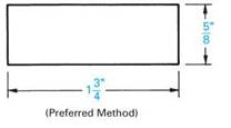
U. S. Customary linear dimensions may be given as whole numbers, fractions, and decimals. Preferred practice is to show dimensions in decimals, Figure 4.3. However, dimensions on drawings for weld fabrication operations are generally shown as fractional dimensions, while drawings for machining operations use decimal fractions. Drawings for both (weld) fabrication and machining use decimals or a mixture of both fractional and decimal dimensions for the appropriate type of operation. Also, current practice is to use a unidirectional dimensioning system, Figure 4.2, rather than the former practice of bidirectional or aligned dimensions, Figure 4.3.
The term common fraction refers to dimensions such as %4, ^2, We, %, %, and V/2 inch, Figure 4.2.
|
|
|
KEY L = LOCATION S = SIZE |
|
FIGURE 4.1 ■ Size and location dimensions. |
|
.500 DRILL |
|
625" |
|
(Nonpreferred Method) |
|
FIGURE 4.3 ■ Decimal dimensions. Bidirectional or aligned dimensions are read from the bottom and right side of the drawing. |
|
|
|
FIGURE 4.2 ■ Fractional dimensions. Unidirectional dimensions are read from the bottom of the drawing. |
|
NOTE: THE SYMBOLф SIGNIFIES DIAMETER. |
|
INCLUDED ANGLE |
|
INCLUDED ANGLE 30c |
|
FIGURE 4.5 ■ Bevel dimension—full length. |
|
FIGURE 4.6 ■ Bevel dimension—partial length. |
|
INCLUDED ANGLE |
Decimal fraction dimensions are used particularly when precision sizes are required. For example, when a drilled hole is dimensioned, a decimal dimension is used, Figure 4.3. The word “drill” may or may not follow the dimension. In cases where the hole is to be reamed, the word “ream” may be applied following the dimensions. If the hole is to be flame cut, the words “flame cut” may follow the dimension. The process specified for cutting the hole generally indicates the accuracy required. In instances where a process is not specified, the choice of method is made by the welder. However, consideration must be given to the accuracy required.
Angular dimensions are given when a line is at an angle to a horizontal, vertical, or another angular line. Examples of each are shown in Figure 4.4. The angle in each case is called the included angle and is shown in degrees, or in degrees and decimal parts of a degree. Although angular dimensions are sometimes shown in degrees and minutes (60°30/), the decimal fraction (60.5°) for minutes is preferred. Refer to Table 4.1.
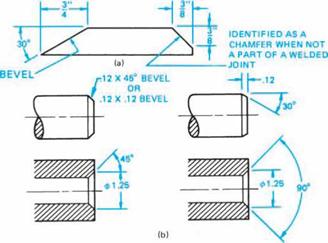
Parts with bevels are commonly found on prints for welders. For joints to be welded, a bevel is a sloping edge that extends the full or partial length of the edge, Figure 4.5 and Figure 4.6. The sharp edge formed is commonly called a feather edge. The root face area along the edge is often called a land. Note that for welding purposes a chamfer is often identified and treated as a bevel.
There are several ways to dimension these features. One common method is by the use of a note with a leader. The amount of the bevel is given as a linear and a degree dimension, Figure 4.5 and Figure 4.6.
"lwA ~ir~
ANGULAR LINE TO A VERTICAL LINE
ANGULAR LINE TO ANOTHER ANGULAR LINE SHOWN IN DEGREES AND IN MINUTES
FIGURE 4.4 ■ Dimensioning angles.
ANGULAR LINE TO A HORIZONTAL LINE
60.5
~лг~
ANGULAR DIMENSION SHOWN WITH A DECIMAL FRACTION (EQUAL TO 60°30')

|
MIn. |
Deg. |
MIn. |
Deg. |
MIn. |
Deg. |
MIn. |
Deg. |
MIn. |
Deg. |
MIn. |
Deg. |
|||||||||||
|
1 |
.0166 |
и |
.1833 |
21 |
.3500 |
31 |
.5166 |
41 |
.6833 |
51 |
.8500 |
|||||||||||
|
2 |
.0333 |
12 |
.2000 |
22 |
.3666 |
32 |
.5333 |
42 |
.7000 |
52 |
.8666 |
|||||||||||
|
3 |
.0500 |
13 |
.2166 |
23 |
.3833 |
33 |
.5500 |
43 |
.7166 |
53 |
.8833 |
|||||||||||
|
4 |
.0666 |
14 |
.2333 |
24 |
.4000 |
34 |
.5666 |
44 |
.7333 |
54 |
.9000 |
|||||||||||
|
5 |
.0833 |
15 |
.2500 |
25 |
.4166 |
35 |
.5833 |
45 |
.7500 |
55 |
.9166 |
|||||||||||
|
6 |
.1000 |
16 |
.2666 |
26 |
.4333 |
36 |
.6000 |
46 |
.7666 |
56 |
.9333 |
|||||||||||
|
7 |
.1166 |
17 |
.2833 |
27 |
.4500 |
37 |
.6166 |
47 |
.7833 |
57 |
.9500 |
|||||||||||
|
8 |
.1333 |
18 |
.3000 |
28 |
.4666 |
38 |
.6333 |
48 |
.8000 |
58 |
.9666 |
|||||||||||
|
9 |
.1500 |
19 |
.3166 |
29 |
.4833 |
39 |
.6500 |
49 |
.8166 |
59 |
.9833 |
|||||||||||
|
10 |
.1666 |
20 |
.3333 |
30 |
.5000 |
40 |
.6666 |
50 |
.8333 |
60 |
1.0000 |
|||||||||||
|
TABLE 4.1 ■ Minutes converted to decimals of a degree. |
|
FIGURE 4.7 ■ Methods of dimensioning bevels. |
Another method for dimensioning bevels is through the use of extension and dimension lines. The sizes may be given as two linear dimensions or as one linear and one angular dimension, Figure 4.7(a). When only a portion of the total edge is cut away at an angle for purposes other than welding, the edge is identified as a chamfer. Examples of bevels are shown in Figure 4.7(a) and Figure 4.7(b). Note that the symbol “X” included with the dimensions signifies places, times, or by. For example, 4X (times or places), and 4" X 4" (by).


 Опубликовано в