Oblique Sketching
 9 марта, 2014
  Oleg Maloletnikov
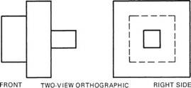
 To develop an oblique drawing, an orthographic view of the object is first drawn that best describes the shape and shows the most detail of the object. For example, the front view of the three-view orthographic drawing of the T-support shown in Figure 2.6 is selected since it shows the shape of the object best.
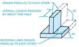
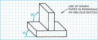
After completing the orthographic view, draw parallel receding lines at about 45° angles from the corners of the view (either to the right or to the left), as shown in Figure 2.7 and Figure 2.8, to develop the three-dimensional effect. Receding lines are drawn to the right for developing a right oblique drawing and to the left for developing a left
|
FIGURE 2.6 ■ Three-view orthographi drawing of a fabricated T-support. |
oblique drawing. Lines are not usually shown for any part of the object n^i mr о / ,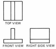 , ,
, ,
FIGURE 2.6 ■ Three-view orthographic that is not visible. The extent of the receding lines is about one-hall the, . r Г1 . j
drawing of a fabricated
length that would be shown for an orthographic drawing. This is so T-suppoit
that the sketch will appear to be true to the original form of the object.
The oblique sketch is completed by repeating the same lines shown on the original orthographic view at the terminal points of the receding lines. Note that, on occasion, broken lines may be used to show hidden edges in order to better visualize the object.
|
|
|
FIGURE 2.7 ■ Right oblique (receding lines drawn to right). |
|
|
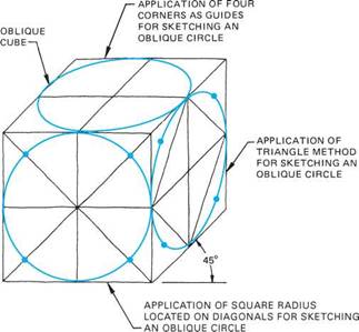
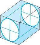
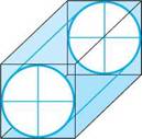
Oblique sketches may require the sketching of oblique circles. Variations of oblique circles and how they may be constructed are shown in Figure 2.9. The procedure used for sketching the oblique circles shown in the oblique cube is the same as that given previously for developing a regular circle. Essentially, the procedure followed is to locate points on a rectangle to which a series of arcs is drawn to form the oblique circle.
|
FIGURE 2.8 ■ Left oblique (receding lines drawn to left). |
FIGURE 2.9 ■ Variations of oblique circles and methods used for sketching each.
|
|
|
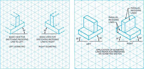
FIGURE 2.10 ■ Preliminary view for sketching isometric drawing of a fabricated T-support. |
|
FIGURE 2.11 ■ Left and right isometric sketches of a fabricated T-support. |
|
|
Isometric Sketching
To develop an isometric sketch, isometric graph paper is preferable. An isometric sketch has all of its surfaces shown at 30° angles. In the initial preparation of the sketch, a view of the object that best shows its shape and detail is selected and sketched at a 30° angle, Figure 2.10.
|
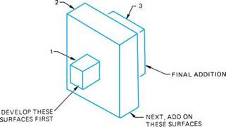
FIGURE 2.12 ■ Method used for developing an isometric sketch having surfaces on different planes. |
After completion of the basic view, Figure 2.10, parallel receding lines are sketched at 30° angles from each of the corners, Figure 2.11. Only those lines that represent the visible part of the object are shown. The sketch is completed by drawing the back edges at points that approximate the size of the object. Receding lines are reduced in length (foreshortened) to about two-thirds of the orthographic line length.
In cases where surfaces of the object are on different planes, a sequence is followed in developing the isometric sketch, starting from the front face and developing each portion progressively to the back face, in effect building upon the preceding portions, Figure 2.12.
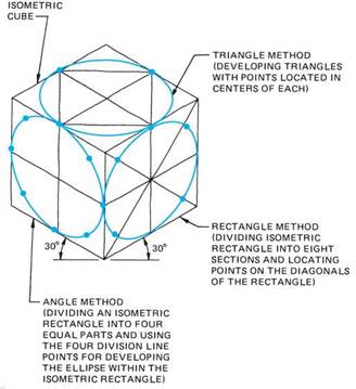
For sketching isometric circles, the same basic techniques are applied as for sketching a regular circle. Variations of the isometric circle and how they are sketched are illustrated in Figure 2.13. For sketching isometric and oblique cyclinders, refer to Figure 2.14.
|
FIGURE 2.13 ■ Variations of isometric circles. |
|
|
|
FIGURE 2.14 ■ Method for developing cylinders. |
|
|
|
(a) ISOMETRIC (b) OBLIQUE |

 Опубликовано в