Notes and Specifications
 13 марта, 2014
  Oleg Maloletnikov
 |
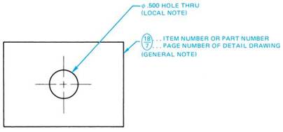
FIGURE 3.1 ■ Application of a local note. |
In many cases, it is not possible to give all the information needed on a print by the combined use of lines and dimensions. To provide additional information, notes and specifications are used.
A note is lettered information (in capital letters) concerning the details of construction. The note explains, specifies, or refers to the material and/or process needed to make the part. To conserve space on the print, and to save time in preparing the drawing, it is often shown as an abbreviation or symbol.
When a note applies to a particular part on an object, it is called a local note. Such a note is placed near
one of the views representing the part. A leader indicates the exact point of reference, Figure 3.1. A general
note applies to the drawing as a whole and is placed in an open space away from the views so that it can be seen readily.
Examples of general notes are:
1. “Unless otherwise indicated, all fillet welds are 3/8" size.”
2. “Unless otherwise indicated, root openings for all groove welds are 3/1б".”
|
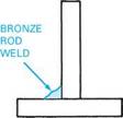
SPECIFICATION A = NO. 20, 1/4" BRONZE ROD |
3. “Unless otherwise indicated, all welds are to be made in accordance with specification A.”
|
|
|
|
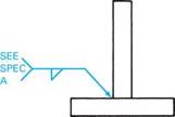
When a note specifies the material required, the welding process to be used, the type and size of electrode, and/or the kind and size of welding rod, it is called a specification. For example, in Figure 3.2 the letter A refers to specification A.
In this case, specification A in the tail of the arrow indicates that No. 20, %" bronze rod is to be used for the weld.
|
SYMBOL SIGNIFICANCE |
Specifications are often located near the views to which they refer. However, when many specifications are required, they are included on a separate sheet and referenced to the drawing. FIGURE 3.2 ■ Application of a specification.
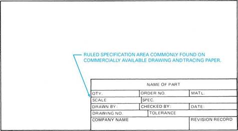
When a specification is general and applies to all or several views, it may be placed within a ruled space called a title block. It is usually denoted as such by prefacing the information with the word “specification.” However, when specifying materials, the word “specification” is not necessarily used, but is implied. Typical title blocks are shown in Figure 3.3. The information that may be included in the title block consists of:
1. Name of part or project
2. Quantity required
3. Order number
4. Material
5. Scale size used
6. Specification (general)
7. Drawn by
8. Checked by
9. Drawing number
10. Date
11. Tolerances
12. Company name
13. Revision record
The standard sizes of commercial mechanical drawing sheets are identified by the letters A through E.
A = 81/2" X 11"
B = 11" X 17"
C = 11" X 22"
D = 22" X 34"
E = 34" X 44"
These letters may or may not be included as part of the drawing identification number.
|
|
|
DATE |
SYM |
REVISION RECORD |
AUTH. |
DR. |
CK. |
|
TOLERANCES (EXCEPT AS NOTED) |
AUTOMATED DYNAMICS CORP. |
||
|
DECIMAL ± |
SCALE FULL |
DRAWN BY [_ J SI Y approv'd byr. paYACK |
|
|
FRACTIONAL ± |
TITLE ROTARY UNION RETAINING NUT |
||
|
ANGULAR ± |
DATE |
DRAWING NUMBER 89 919 |
|
|
TOLERANCES (EXCEPT AS NOTED) |
REVISIONS |
AUTOMATED DYNAMICS CORP. |
||||
|
NO. |
DATE |
BY |
||||
|
DECIMAL .XX +.01 + .XXX+.005 |
1 |
BAR, STOP |
||||
|
2 |
||||||
|
F RACT IONA L ± |
3 |
DRAWN BY DG |
SCALE j. j |
MATERIAL aluminum |
||
|
ANGULAR ± |
4 |
CHK’D |
DATE |
DRAWING NO. 896I5322504 |
||
|
5 |
TRACED |
APP'D |
FIGURE 3.3 ■ Typical drawing master showing ruled title blocks.
|
|
Н'-|
|
|
UNIT 3 REVIEW
Refer to the drawing, Corner Bracket, page 20.
1. What is the name of the part? 10. What three types of lines are used to aid in
dimensioning?
2. How many are required?
3. What is the order number?
11. What item can be called a general note specification?
4. What type of material is used?
12. What item would be identified as a local note?
5. How many views are shown?
13. How many holes are to be drilled?
6. Name each of the views shown.
14. How deep is each hole to be drilled?
15. What is the diameter of the holes?
7. Which view shows the shape of the object best? 16. How many pieces are required to fabricate the
part?
8. In which views are leaders used?
17. What do the hidden lines in each of the views represent?
9. Name each type of line used in the drawing.
18. What is the significance of the note, “Break All Sharp Edges”?
19. Identify an item within the title block that would be described as a specification.


 Опубликовано в