Basic Lines and Views
 2 марта, 2014
  Oleg Maloletnikov
 BASIC LINES
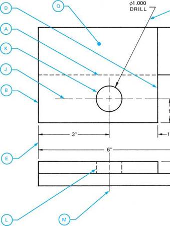
There are several different types of lines used on a print and each has a different meaning. To be able to interpret a print, the reader should have knowledge of these lines. Table 1.1 can be used as a reference for the common line types usually found on a print. Note that the purpose of each line deals with either the shape of the object or its dimensioning.
BASIC VIEWS
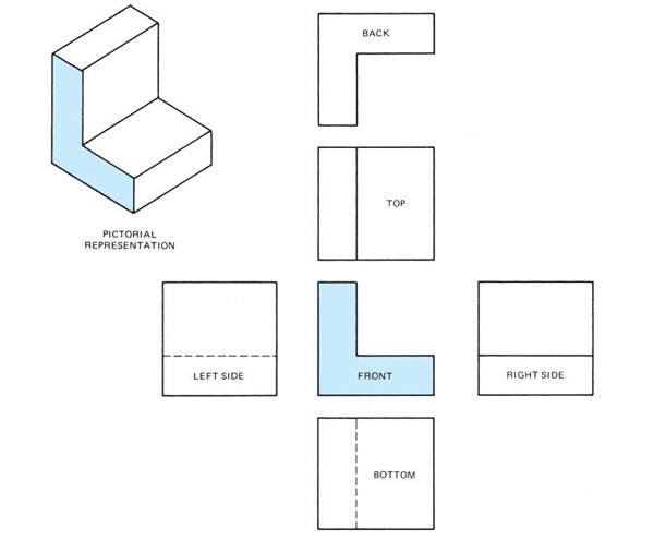
Drawings are made to describe the object in sufficient detail to permit fabrication. Orthographic projection is the method employed to do this. By this method the exact form of the object is shown by various views of the object arranged in a particular order. The selection and arrangement of these views is shown in Figure 1.2. Note the relationship in the placement of the views in the figures.
|
Type of Line |
Description |
Purpose |
|||
|
OBJECT LINE |
Thick solid line. |
To show the visible shape of a part (outline of object). |
|||
|
HIDDEN LINE |
Broken line of medium thickness. |
To show edges and outlines not visible to the eye. |
|||
|
CENTER LINE |
Fine, broken line made up of a series of short and long dashes alternately spaced. |
To show the center of circles, arcs, and symmetrical objects and to aid in dimensioning these parts. |
|||
|
ЕХТЕГ LINE |
VISION EXTE LINE |
IN SION |
Extension lines are fine lines that extend from the object with a slight break between. Dimension lines are fine lines with arrowheads, unbroken except where the dimension is placed. |
Extension lines show dimensioning points. Dimension lines touch the extension lines and show distance given by the dimensions. |
|
|
DIMENSION LINE |
|||||
|
LEADER^ ^ |
Fine, straight line with an arrowhead or round solid dot at one end. It is usually drawn at an angle. |
Points directly to a surface for the purpose of dimensioning or adding a note. A dot is used at the end of the straight line where reference is made to a surface area. |
|
TABLE 1.1 ■ Common types of lines used on a print. (continued) |
|
To indicate where an imaginary cut is made through the object. The arrow points in the direction in which the section should be viewed. Letters next to the arrowheads identify the section in cases where more than one section is shown on the drawing. These lines are oriented vertically, horizontally, or at the actual angle at which the part is drawn. |
|
The preferred cutting plane line is a heavy, broken line made up of a series of one long and two short dashes alternately spaced. Arrowheads are placed at right angles to the cutting plane line as shown. Alternate cutting plane lines are a solid heavy line or a series of long dashes. |
|
Series of fine lines—solid or solid and broken—arranged in specific patterns. They may be shown either straight or curved. When shown straight, they are usually drawn at a 45° angle. However, this angle will vary when applied to adjacent parts. |
|
To indicate the imaginary cut surface referred to by the cutting plane line; to represent various kinds of materials. |
|
Heavy, broken line made up of a series of long and short dashes alternately spaced. |
|
CHAIN LINE |
|
Indicates the location and extent of a surface area. To show a short break (to conserve space on a drawing); to show a partial section. |
|
SHORT |
|
Heavy, irregular line drawn freehand. |
|
BREAK LINE |
|
Ruled, light line with freehand zigzags. |
|
To show a long break (to conserve space on a drawing). |
|
LONG BREAK LINE |
|
To show alternate positions of a part; to show relationship of existing part to new part; to show machined surfaces. |
|
Light, broken line made up of a series of one long and two short dashes. |
|
PHANTOM LINE |
|
TABLE |
■ Common types of lines used on a print. (concluded)
Figure 1.1(a) shows two types of pictorial drawings of a three-dimensional block and Figure 1.1(b) shows three two-dimensional views of the block. By examining each of the three views in Figure 1.1(b), an accurate picture of the shape of each face can be formed. In this case, three views are used to describe the object. Note that the views have a definite arrangement. The top view is placed directly above and in line with the front view; the right side view is placed to the right of and in line with the front view. This arrangement of views is in accordance with third angle orthographic projection referred to in Figure 1.1.
There is no limitation on the number of views that may be used to describe an object. Usually, three properly selected views are sufficient. In cases where more views are needed to illustrate the shape clearly and to make dimensioning easier, the bottom, left side, or back views can by used. Simple parts can be completely described with only one or two views.
|
|
|
OBLIQUE |
|
ISOMETRIC |
|
TOP |
|
FRONT |
|
(b) ORTHOGRAPHIC PROJECTION (IN THREE VIEWS) |
RIGHT SIDE
(a) PICTORIAL
FIGURE 1.1 ■ Methods of representing an object.
|
FIGURE 1.2 ■ Locations and alignment of views that may be selected to describe an object on an orthographic drawing. |
It should be noted that the front view usually gives the best indication of the shape and detail of the object. This does not mean that the front view necessarily shows the front of the object. For example, if a welding torch is represented on a print, the front of the torch is not shown as the front view since it does not show the shape of the torch as well as a side profile of the torch. Therefore, to simplify the reading of the print, the profile selected for the front view is generally that which best describes the most detailed shape of the object.
All views have a particular position with respect to each other, and have either a horizontal or vertical alignment. These positions, illustrated in Figure 1.2, should be learned.
|
|
NOTE: ф IS USEDTO DENOTE DIAMETER
|
QTY. NO. 25 |
ORDER NO. 8 |
|
MAT. COLD ROLLED STEEL |
SCALE: 1/2" = 1" |
|
DRAWN BY: L GRADY |
|
|
DWG. NO. |
DATE: |
JIG SUPPORT
|
|
|
|
UNIT 1: REVIEW B
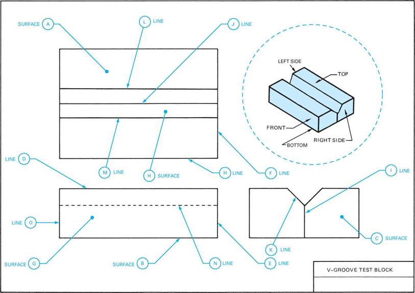
Refer to the drawing, V-Groove Test Block, page 6.
1. Why are three views used to show the object? 10. Which line in the top view represents surface
© in the front view?
|
2. Name each of the views shown. |
11. Is surface (3 shown in the top view?
12. What does the top view have in common with the front view?
3. In which two views is the length of the object the same?
13. What does the front view have in common with the side view?
4. In which two views is the width of the object the same?
14. What do the top view and right side views have in common with respect to the front view in terms of alignment?
5. In which views is the thickness of the object the same?
6. Which line represents surface (A in the front view?
7. Which line represents surface ^ in the right side view?
15. What do lines (L and represent?
16. What does the following symbol indicate?
17. Which line represents N in the top view?
8. Which line represents surface © in the front view?
18. What surface does (3 represent?
|
19. What surface does © represent? |
9. Which line represents surface © in the top view?


 Опубликовано в